Bed Platform and Z Gantry
The print system supports two different setups for the Z-gantry; a two-motor setup common in cube-style printers and a three motor system for completely automated bed leveling. Each has significantly different requirements for attaching to the vertical rods as well as to the bed platform.
The three motor system requires:
- Three NEMA 17 steppers
- A control board capable of driving three independent Z steppers
- Five (or Six) 8mm smooth rods and bearings
- Three 8mm threaded rods and nuts
- Three threaded balls and cup magnets
- Two extrusions and an aluminum plate
The two motor system requires:
- Two NEMA 17 steppers
- Four 8mm smooth rods and bearings
- Two 8mm threaded rods and rod nuts
- Four extrusions and an aluminum plate
The two motor system can be configured to use independent Z stepper drivers (recommended) or can use a single driver for both motors - and with some ingenuity easily adapted to a linked Z setup. An in-depth overview of the three stepper setup is available in this video. The two motor setup is far more common and far less demanding from a cost, configuration, and electronics perspective but you'll have to deal with bed leveling screws where the three motor solutions eliminates the need for any manual bed leveling.
Two-Motor Solution
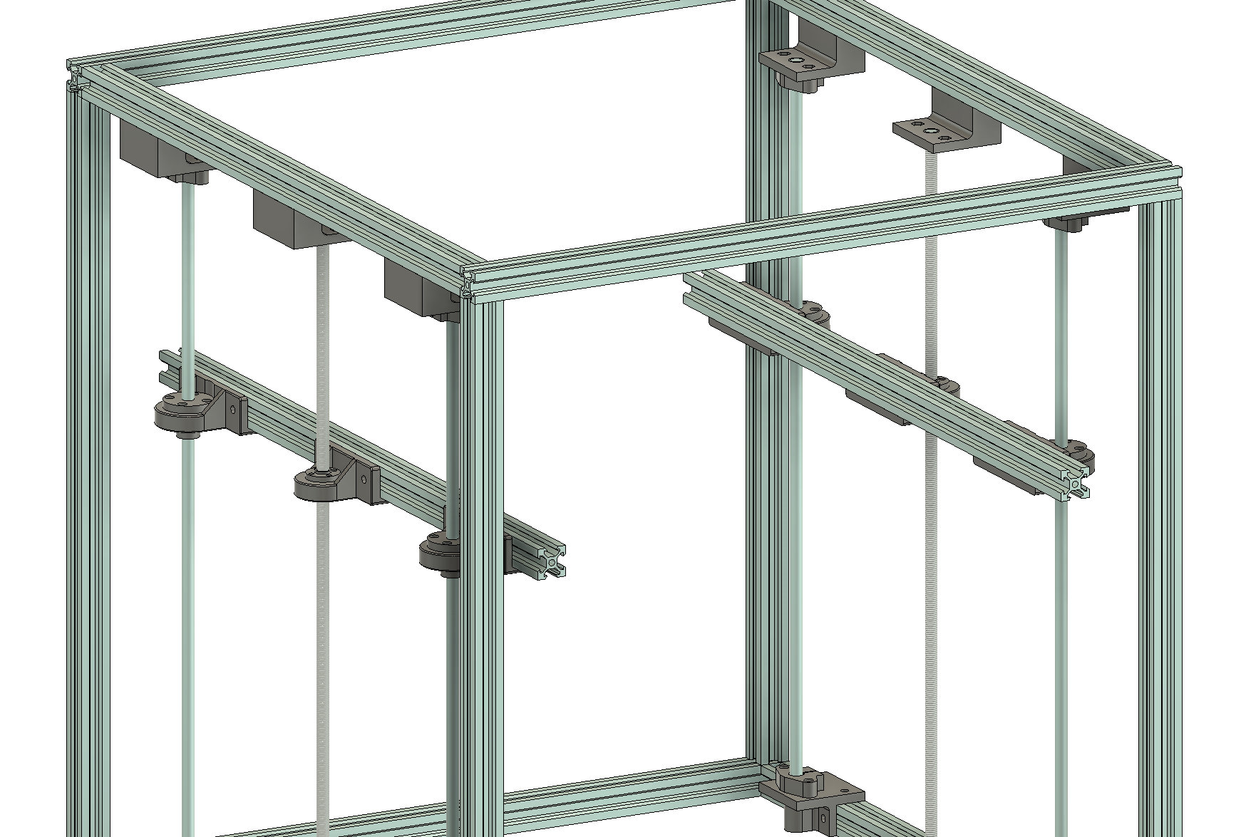
The two-motor solution is common in cube style printers. While the build platform varies it's generally a rigid square structure supported on the left and right sides by a set of two smooth rods to keep the platform parallel to the Z axis and one threaded rod to position the platform the correct distance from the hot end. Given the dramatic advantage of dual independent steppers vs shared steppers or even linked Z I advise implementing dual independent Z over linked Z or shared steppers however the rods can be decoupled from the motors so any setup is possible.
The length of the threaded and smooth rods is based on the build height. Assume that a minimum of 30mm of rod will be 'lost' to mounting and then another 40-80mm will be required for the bearings, platform structure, and bed plate and surface. You can use longer rods as both top and bottom mounts have holes that allow the rods to sit higher or lower (within reason).
I have two options for mounting the motors and shafts to the frame. You can either mount the motor to the frame and the threaded rod directly to the motor shaft using a spring coupling or you can mount the threaded rod directly to a pillow bearing and use a timing belt and pulleys to rotate the shaft (also useful for linked Z). I recommend using the belted option as I prefer a solid mounted threaded rod but the shaft mount is more popular and will save a few bucks on parts.
As an example, let's assemble the belted solution:
- Print 4x of Linear Rod Guide Base, Linear Rod Guide Top, Bed Platform - Linear Rod Hearing Mount, Bed Plate Mount
- Print 2x of Threaded Rod Pillow Base, Threaded Rod Pillow Top, Z Motor Mount - Tabbed, Bed Platform - Threaded Rod Nut Mount
- Prep all bases, tops, and platform mounts by attaching linear rod shaft supports to the linear tops/bottoms, pillow bearings to the threarded tops/bottoms (tops are optional), LM8UU bearings to the platform linear bearing mounts, and T8 lead screw nuts to the platform threaded rod mounts.
- Align and attach the front Linear Rod Guide Bases on the bottom left and right extrusions. The distance of base from the front extrusions should be at least 40mm and I recommend printing a spacer of some sort to ensure spacing is precise and consistent. Do the same for the Linear Rod Guide tops.
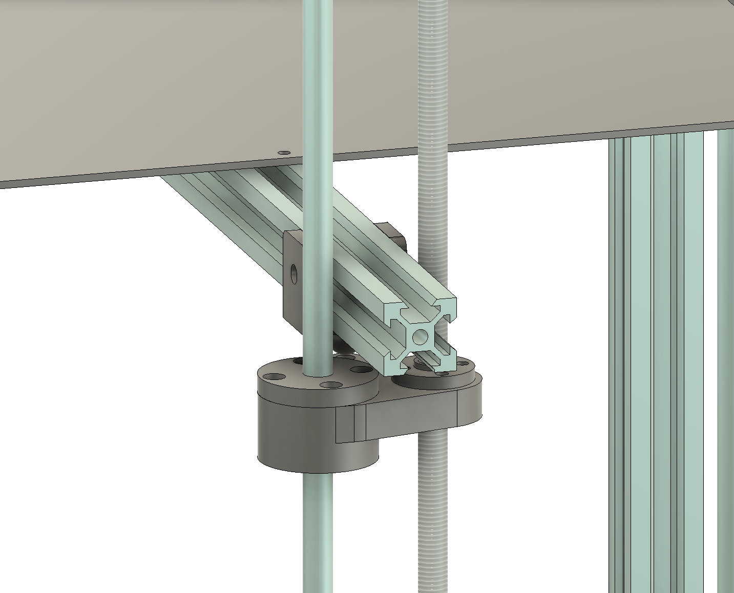
- Align and attach the threaded rod bases and tops with the middle of the left and right bottom and top extrusions. Getting the mounts pefectly aligned to the middle of the extrusion is not essential however ensuring that the tops and the bottoms are perfectly align vertically is very important.
- Feed the linear rods and threaded rods through the top mounts. Slide the platform linear rail mounts onto the rods and screw the threaded platform mounts onto the threaded rod. Slide the GT2 timing pulley and belt onto the threaded rods. Then insert the rods through the bottom mounts - ensuring that no more than ~2cm of rod sticks up above the plate on the top mounts - and tighten the grub screws and clamps.
- Attach the stepper motors to the motor mounts and secure the timing pulley to the motor shaft. Attach the motor mount to the frame such that the GT2 loop aligns with both the timing pulley on the threaded rod as well as the timing pulley on the motor shaft. The cable loop should be perfectly horizontal. Tighten the grub screws on the pulleys.
- Your left and right gantry is now attached. We can proceed with building the bed platform
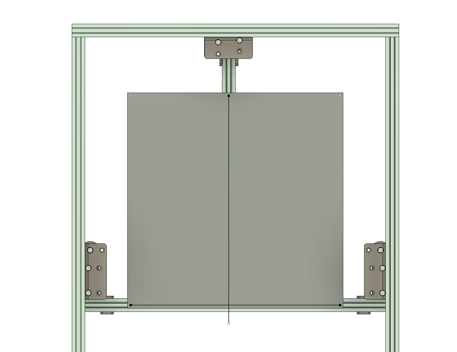
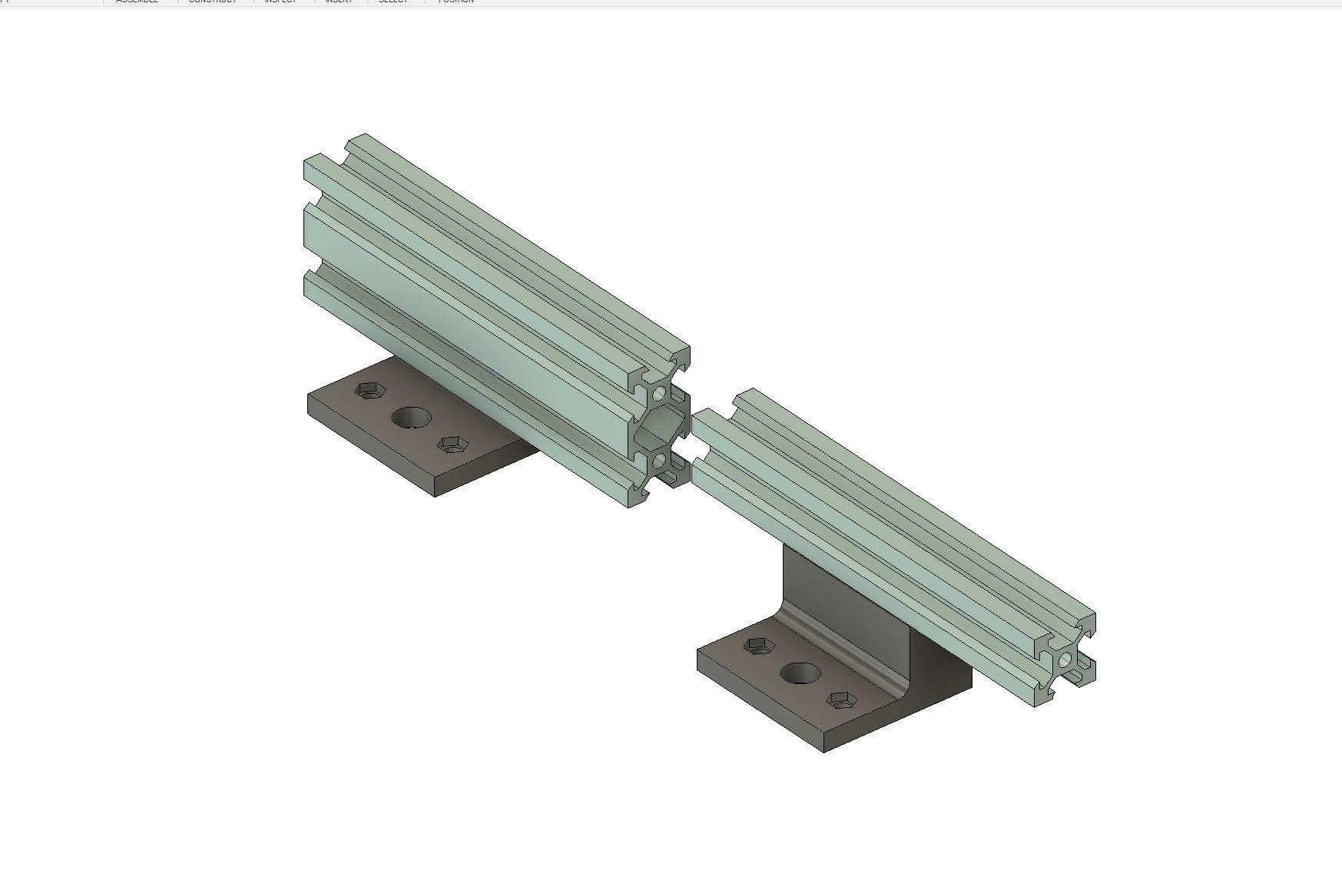
For the bed platform we're going to use four 2020 extrusions. Two extrusions will attach platform mounts on our installed Z gantry and two will run perpendicular to those and align to our build plate holes. The extrusions can be left 'long' and stick out the sides of the printer however you need to take care that you're not snagging cables or ramming the platform into stuff on your desk or floor.
- Attach a 2020 extrusion to the platform linear mounts and threaded mounts on the left side such that the extrusion's center is aligned with the threaded rod mount. Repeat for the right side. Here is where you may want to measure and trim the extusion such that it is a) longer than your bed plate and b) shorter than your printer frames interior depth.
- Attach two bed plate mounts to the front bed platform extrusion such that the mounts align with the mounting holes on your bed plate when the bed plate is centered on the rod. Do the same for the rear bed platform extrusion.
- Lay the extrusions with the bed plate mounts on top of and perpedicular to the extrusions mounted to the rods such that a) the four bed platform holes align with the bed plate mounts and b) the extusions are centered with the printer frame. Use 2020 Cross Supports and/or 2020 T Joints to mount the perpendicular extrusions to each other. In the future you can adjust the Y positioning of the bed to account for travel limitations of your printer head.
- Mount the build plate to the build plate mounts using standard mounting screws, springs, and nuts.
There are alternate platform attachment brackets as well in order to accomodate multiple construction scenarios and dimensions, for example:
Note that you could cut the 2020 extrusions so that the extrusions are coplanar and use standard 2020 corners to build an even more rigid platform that is also 20mm shorter however cutting 2020 is permanent and can be difficult without the right tools. I would suggest 'roughing in' the build plate using the above instructions and only cut and permanently fit the extrusions once you are confident on the dimensions. If your extrusions are larger than your printer frame pay special attention to your wire routing and electronics placement so that nothing gets caught on the extrusions anywhere in the full Z range.
Three-Motor Solution
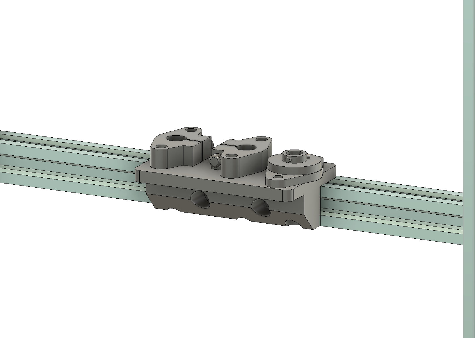
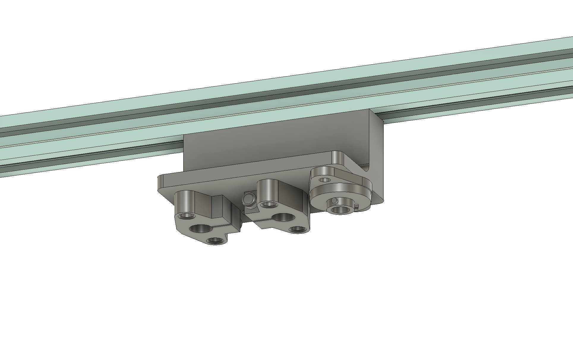
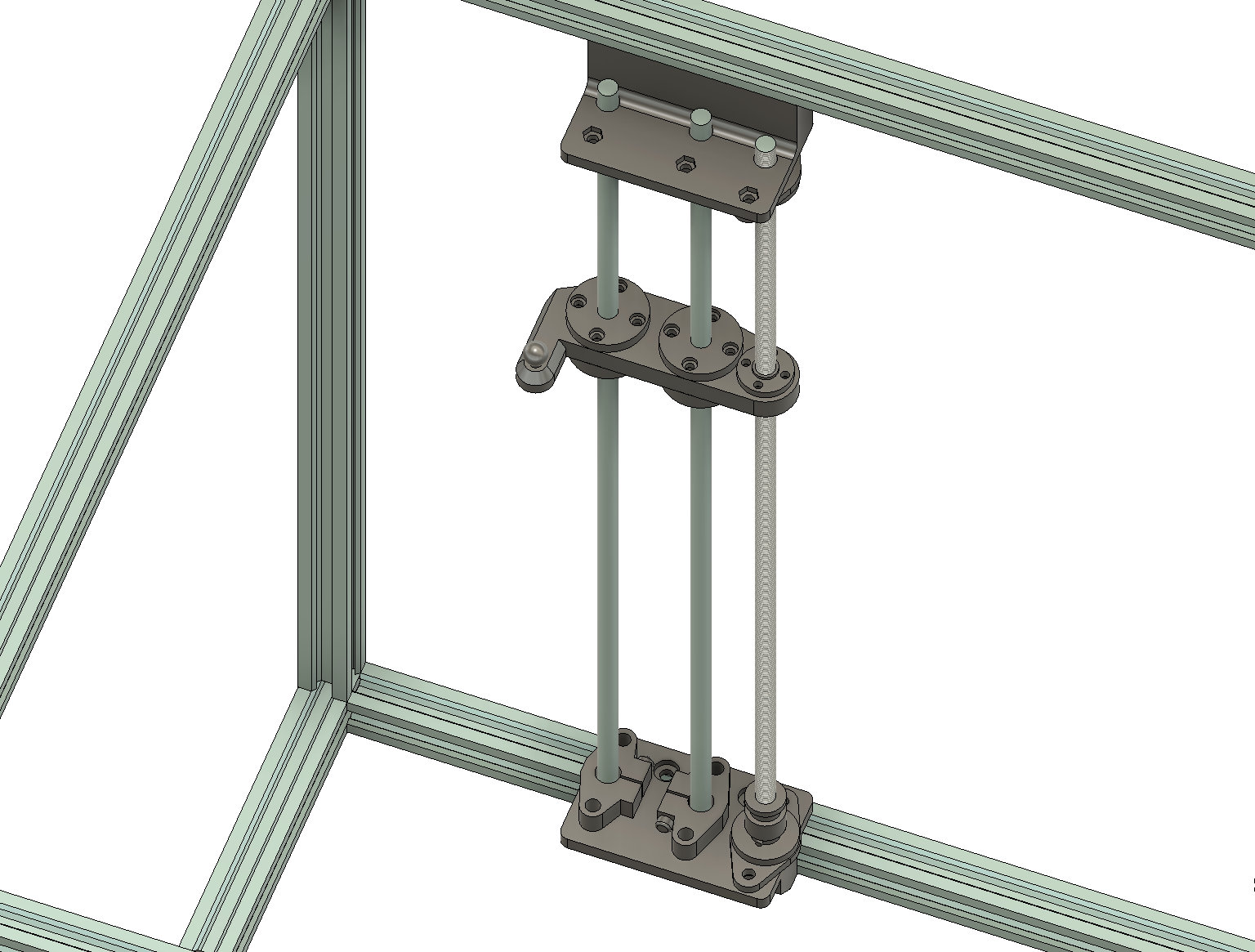
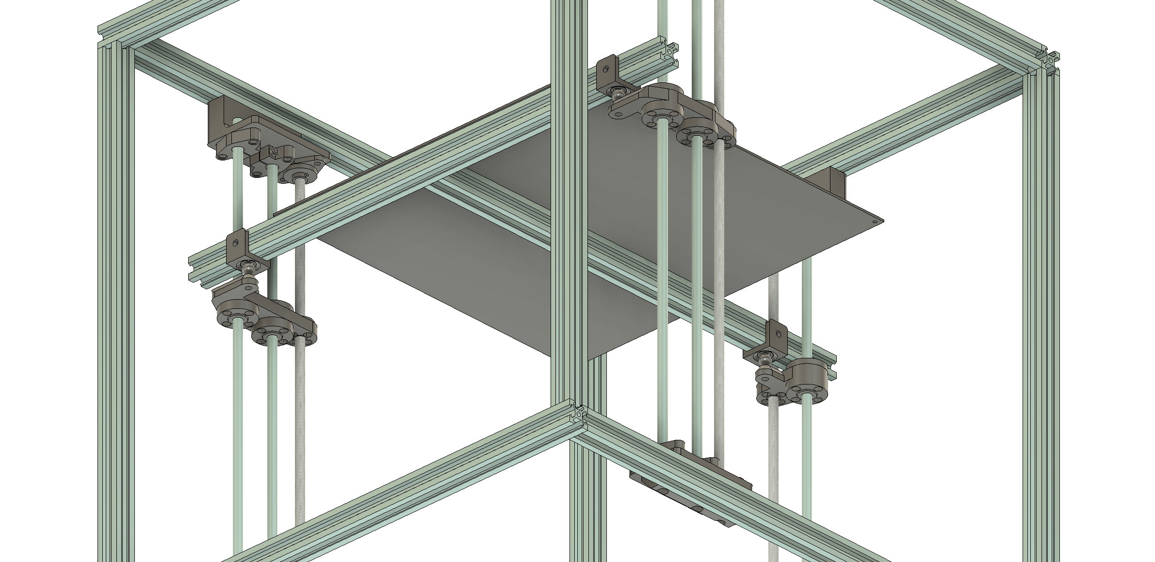
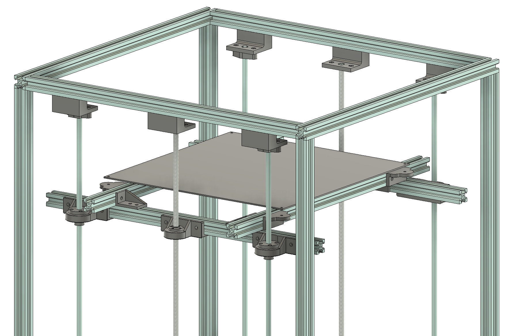
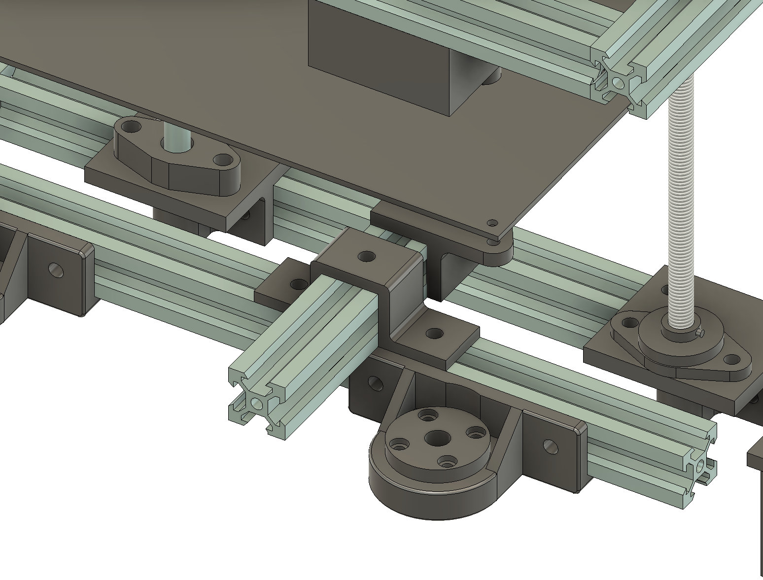
The three-motor solution is more complex and expensive than the two motor solution but it completly eliminiates the bed-leveling activity! Since three points make a plane, three indepent Z motors can use the same tilt adjustment mechanics that balance a two-motor design along the X axis to balance the entire build plate along the X and Y axes. Three motor solutions are often reserved for more expensive and complex printers and often the solutions reflect that by using more robust but expensive components (like linear rails). The three motor solutions in the BigPlans print system stick with cheaper linear rods and threaded rods while maintaining sufficient stability and functionality for a reasonably priced printer.
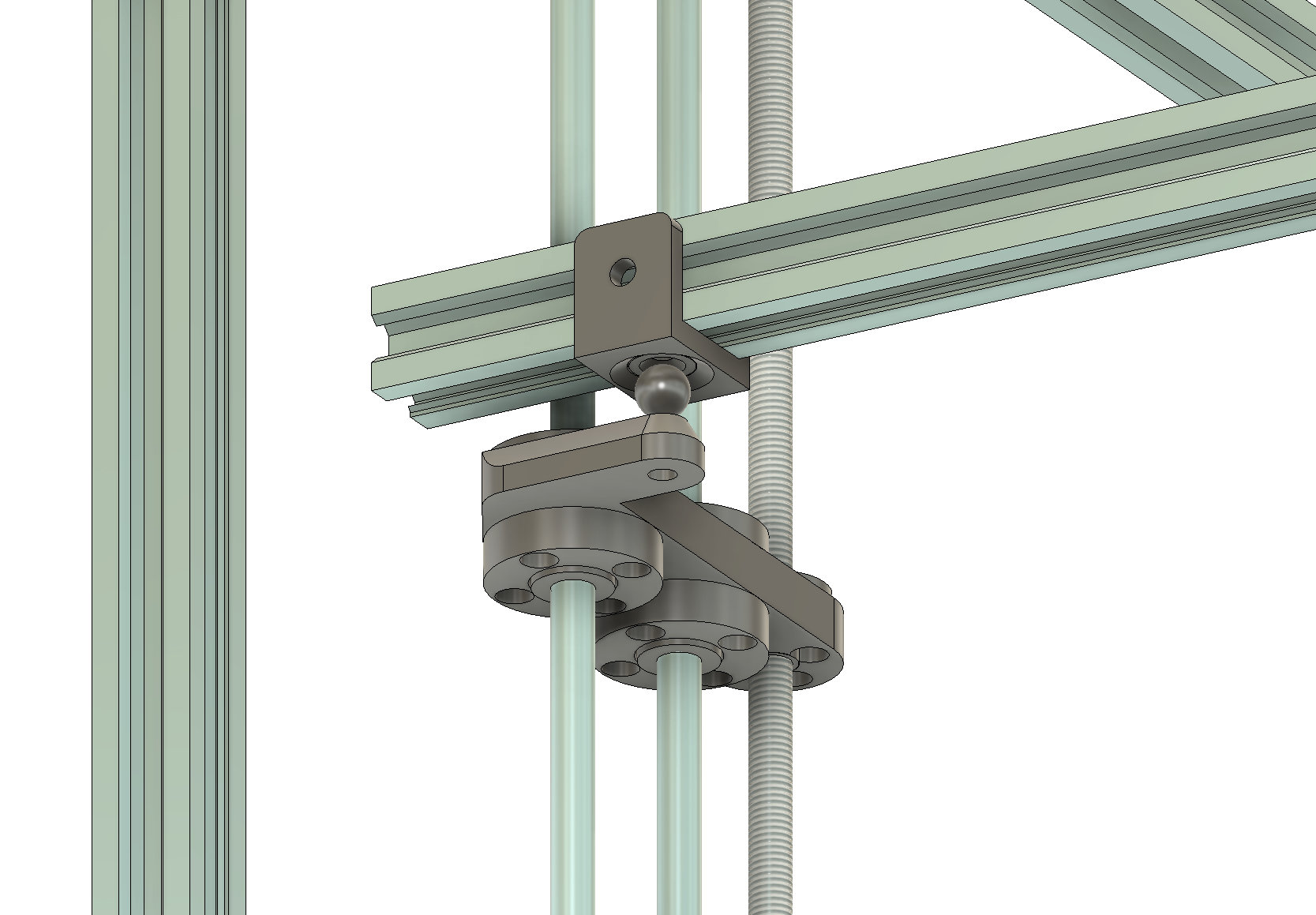
An additional complexity in a three motor solution is that with a two motor solution the expectation is that the build platform is perpendicular to the linear and threaded rods. That means the rods can be rigidly mounted to the bed platform and - to some extent - contribute to keeping the bed platform level. Any small discrepancy in the left/right balance - as well as tilt along the Y axis - is accounted for with the bed leveling screws. In a three motor solution the motors adjust to account for any discrepancy in bed leveling and even if you were to utilize bed leveling screws they would be ineffectual as the motors would 'undo' any adjustments. Therefore, there is no guarantee that the bed platform will be perfectly perpedicular to the rods and the rods were to be rigidly mounted some amount of tension would be introduced when adjusting for tilt. That tension could lead to binding or even bent rods over time.
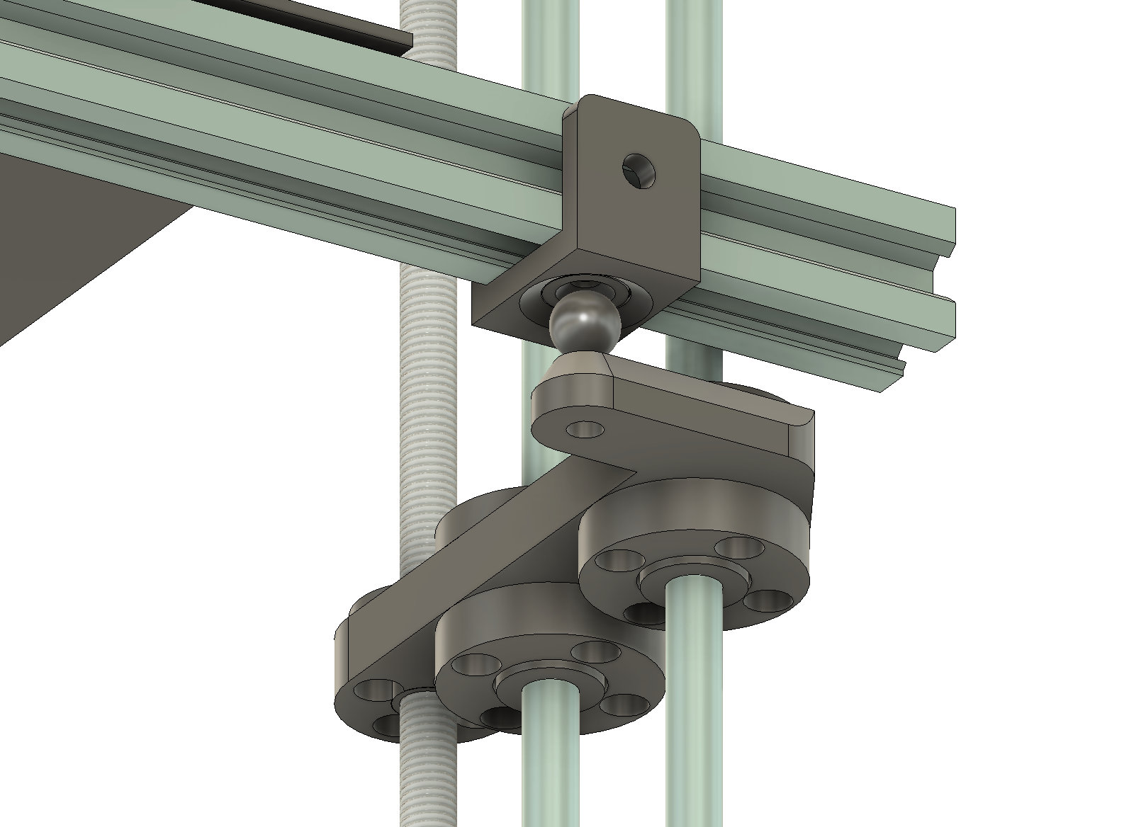
The solution I've implemented is inspired by the RatRig line of printers. It consists of threaded metal balls that attach to carriages that ride along the rods using rigid bearings and nuts then cupped magnets that attach to the bed platform. The balls can then rotate and stretch a bit to account for angular tilt correction. While the RatRig solution advertises a significant amount of travel and angle - and makes for a really cool demo - that kind of range is not required for standard printers and would not work where the sensing probe is only a few mm from the extruder nozzle (ie: 45 degrees of travel does not matter when you only have 15 degrees of range between the sensor and nozzle).
I've dedicated an entire video to this three-motor Z gantry but we'll go through it in detail here as well.
As with the two motor solution the 2020 extrusions can be trimmed to fit within the boudnary of the frame however I still recommend running with the longer extrusions before permanently altering them.
2040 Gantry
While 2020 is the most common extrusions used for the XY Gantry some may opt to use 2040 extrusions. 2040 extrusions oriented vertically would push the top gantry mounts lower relative to the X-Carriage so a different top mounting solution must be used. Top mounts suffixed with '40mm' should be used if your XY gantry uses vertically oriented 2040 extrusions.
Bed Heater
There are many options for bed heaters and the printer system makes no assumption on what kind of heater you will use. Silicone heat pads are the most common aftermarket solution but they come in numerous electrical options. The most common setup is to use the sticky backing of the silicone pad and mount it to the bottom of the build plate however I am personally uncomfortable with relying on stick backing to keep the plate attached to the plate. Instead I use a layer of corkboard on top of the plate, then the silicone heater, then a sheet of glass and/or PEI all held together with binder clips.
I have produced an entire video on bed heater options and is a good reference if you are unsure of the bed types and capabilities you are looking for.
Purchasable Items:
8mm Smooth Rods*
8mm Smooth Rod Clamps*
LM8UU Smooth Rod Bearings*
T8 Threaded Rods w/Nut*
8mm Pillow Bearing*
2020 Extrusions*
Standard NEMA17 Stepper Motor*
20 Tooth 5mm GT2 Timing Pulley*
20 Tooth 8mm GT2 Timing Pulley*
GT2 Belth Loops (I use 200mm)*
10mm m4 Threaded Balls*
12mm Counter-Sunk Magnets*
Zyltech 400mm Aluminmum Bed Kit
Silicone spacers for bed leveling*
Printable Items
Two-Motor Z Gantry
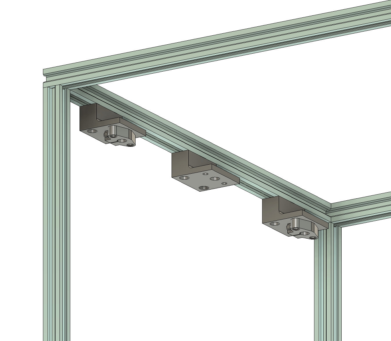
- Smooth Rod Guide Top - mounts to the underside of the upper frame extrusion (2020). Holds an 8mm smooth rod clamp.
- Smooth Rod Guide Top -40mm - mounts to the underside of the upper frame extrusion (2040). Holds an 8mm smooth rod clamp.
- Smooth Rod Bearing Mount - mounts to the bed platform and takes an LM8UU bearing. Use for belted Z motors.
- Smooth Rod Bearing Mount - Motor Mounted Rod - mounts to the bed platform and takes an LM8UU bearing. Use for shaft mounted Z motors.
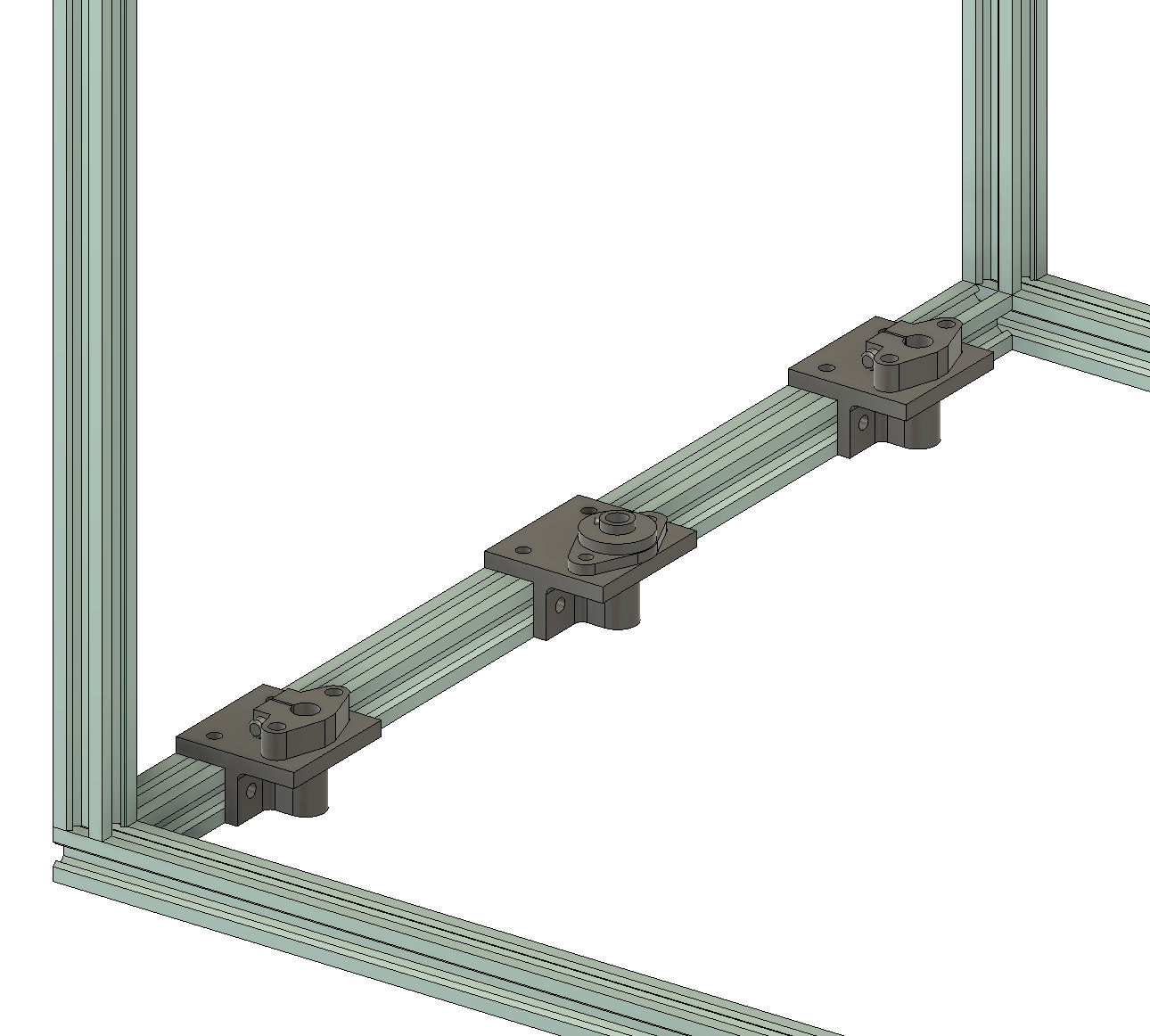
- Smooth Rod Guide Base - mounts to the lower frame extrusion and holds an 8mm smooth rod clamp.
- Threaded Rod Nut Mount - mounts to the bed platform and takes an 8mm threaded rod nut.
- Threaded Rod Pillow Top - mounts to the underside of the upper frame extrusion (2020). Use for belted Z motors.
- Threaded Rod Pillow Top - 40mm - mounts to the underside of the upper frame extrusion (2040). Use for belted Z motors.
- Threaded Rod Pillow Top - Motor Mounted Rod - mounts to the underside of the upper frame extrusion (2020). Use for shaft-mounted Z motors.
- Threaded Rod Pillow Top - Motor Mounted Rod - 40mm - mounts to the underside of the upper frame extrusion (2040). Use for shaft-mounted Z motors.
- Threaded Rod Pillow Base - mounts to the lower frame extrusion and holds a pillow bearing for an 8mm threaded rod. (Note, if using a shaft-mounted threaded rod you will not need this part - only the motor mounts
- 20mm T Joint - used for constrction of build platform.
- 2002 90 degree - used for construction of build platform
- Bed Plate Mount Offset - 2020 mount that takes m3 bed leveling screws - offset to one side.
- Bed Support Platform - 2020 mount that takes m3 bed leveling screws.
- Z Motor Mount - Basic 2020 mount for NEMA17 stepper with an offset tab for extra holding power. Can be used for belted or shaft mounted threaded rods.
- Z Motor Mount untabbed - Basic 2020 mount for NEMA17 stepper. Can be used for belted or shaft mounted threaded rods.
Three-Motor Z Gantry
- Cap Magnet Mount - mount a counter-sunk 12mm round magnet to a 2020 extrusion.
- Corner Magnet Mount - mount a counter-sunk 12mm round magnet at a 2020 corner.
- Straight Magnet Mount - mount a counter-sunk 12mm round magnet along a 2020 extrusion.
- Triple Bottom Mount - Left/Right - mounts to the left/right lower frame extrusion and holds an 8mm pillow bearing and two 8mm smooth rod clamps.
- Triple Top Mount - Left/Right - mounts to the underside of the left/right upper frame extrusion (2020) and holds an 8mm pillow bearing (optional) and two 8mm smooth rod clamps.
- Triple Top Mount - Left/Right 40mm - mounts to the underside of the left/right upper frame extrusion (2040) and holds an 8mm pillow bearing (optional) and two 8mm smooth rod clamps.
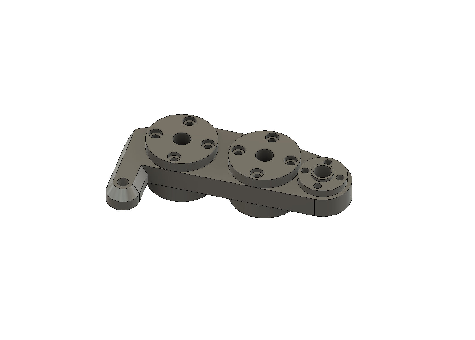
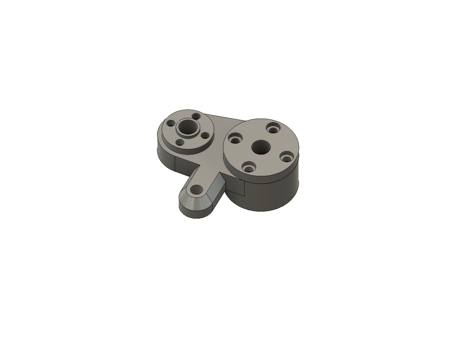
- Triple Bed Mount Left/Right - carriage that ride along the left/right gantry threaded and smooth rods. Uses two LM8UU smooth rod bearings, one T8 threaded rod nut, one 10mm threaded ball/m4 boltand nuts.
- Triple Bed Mount Mid - carriage that ride along the left/right gantry threaded and smooth rods. Uses two LM8UU smooth rod bearings, one T8 threaded rod nut, one 10mm threaded ball/m4 bolt. This version allows the 2020 extrusion to pass between the smooth rods and is useful when you want a three rod rear gantry.
- Double Top Mount - mounts to the underside of the rear upper frame extrusion (2020) and holds an 8mm pillow bearing (optional) and 8mm smooth rod clamp.
- Double Top Mount - mounts to the underside of the rear upper frame extrusion (2040) and holds an 8mm pillow bearing (optional) and 8mm smooth rod clamp.
- Double Bottom Mount - mounts to the lower frame extrusion and holds a pillow bearing for an 8mm threaded rod and an 8mm smooth rod clamp.
- Double Bed Mount - Short - carriage that rides along the rear gantry threaded rod and smooth rod. Uses one LM8UU smooth rod bearing, one T8 threaded rod nut, one 10mm threaded ball/m4 bolt and nuts.
- 20mm T Joint - used for constrction of build platform.
- 2002 90 degree - used for construction of build platform
- Bed Plate Mount Offset - 2020 mount that takes m3 bed leveling screws - offset to one side.
- Bed Support Platform - 2020 mount that takes m3 bed leveling screws.
- Z Motor Mount - Basic 2020 mount for NEMA17 stepper with an offset tab for extra holding power. Can be used for belted or shaft mounted threaded rods.
- Z Motor Mount untabbed - Basic 2020 mount for NEMA17 stepper. Can be used for belted or shaft mounted threaded rods.